HIGHVOLT HVAC POWER FREQUENCY RESONANT TEST SYSTEMS
Features
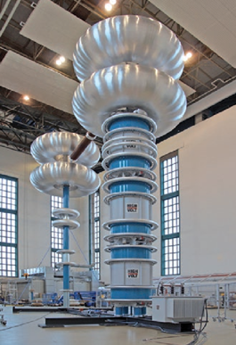
- Resonant test systems are applied for the generation of high- voltage AC of power frequency for routine, type and develop- ment testing of capacitive test objects. There are two types: steel tank type WR and modular insulating case type WRM.
- The main advantage of the resonant test systems is the low power demand because only the losses in the test circuit must be covered by the power supply. Therefore a resonant test system is remarkably lighter and more economic than an AC transformer test system.
- The resonant test systems are characterized by a low PD noise level due to their sophisticated design. The test power and the test voltage can be adapted to customer’s needs and can be increased by a parallel and series connection of reac- tors, as well as by using a virtual electric shaft. The customized design of the test systems makes it possible to arrange the HV components in a space-saving manner.
APPLICATION
The test systems enable testing according to IEC standards, other international standards and customer’s specifications
Main applications are:
- Cable testing on delivery length, cable samples and cable accessories with type WR or WRM
- Applied voltage tests for transformer testing with type WRM
- Current and voltage transformer testing (CTs and VTs) with type WRM
- Capacitor testing with type WR
- Generator and motor testing with type WR
- GIS/GIL and accessories testing with type WRM
Because of their precise sine wave, series
resonant test sys- tems are well
suited for HVAC tests with PD and tan delta measurements.
Resonant test systems also enable tests at other
frequencies, e.g. for instrument transformers, or dyna- mic tests with fast voltage changes for capacitors.
SKU: High Volt
Category: High Voltage Lab Equipment, High Volt
SYSTEM AND COMPONENTS
The system is supplied with
the feeding power from the power network via a switching cubicle (1) [see fig.
3], a voltage regula- tor (2) and an exciter transformer (3). The exciter
transformer is equipped with taps for an ideal adaptation of the output voltage.
In case of tank-type reactors the exciter transformer is built into the tank of
the HV reactor. The HV reactor (4) varies its inductance by a magnetic core
that can be adjusted to a precise distance. The moveable part of the core is
driven by a frequency-controlled motor. The test object (16) is connected via a
HV filter. The filter con- sisting of a blocking impedance (5) and a HV
capacitor (6) has several functions: It reduces the conductor-connected HF
noise for PD measurement, protects the HV reactor in case of a break- down and
acts as a basic load which guarantees resonance if no test object is connected.
The capacitor (6) is the divider for vol- tage measurement (13) and the
coupling capacitor for PD mea- surement (14). For very precise voltage or tan
delta measurement (15) a compressed-gas standard capacitor (7) can be
added.
BENEFITS
- LOW POWER DEMAND DUE TO HIGH QUALITY FACTOR
- LOWEST PD NOISE LEVEL
- HIGHEST VOLTAGES BY CASCADING OF MODULES
- LARGE VARIETY BY SINGLE, SERIES AND PARALLEL CIRCUITRIES
- LOW ACOUSTIC NOISE LEVEL
TECHNICAL PARAMETERS
Systems with metal tank reactors type WR
For cable testing
- Series resonant test systems
- Rated voltages from 35 kV up to 400 kV Rated power from 300 kVA up to 10,000 kVA
For capacitor testing
- Series and parallel resonant test system
- Rated voltage from 6 kV up to 60 kV
- Rated power from 5,000 kVA up to 10,000 kVA
- Dynamic tests optional
For generator and motor testing
- Series and parallel resonant test systems
- Rated voltages from 15 kV up to 60 kV
- Rated power from 300 kVA up to 1,000 kVA
Systems with insulating case modular reactors type WRM
For cable testing
- Series resonant test systems
Rated voltages from 250 kV up to 1,600 kV- Rated power from 1,600 kVA up to 56,000 kVA
For power transformer, GIS/GIL, and cable accessories testing
- Series resonant test systems
- Rated voltages from 250 kV up to 1,600 kV
- Rated power from 1,000 kVA up to 22,500 kVA
For instrument transformer testing
- Series resonant test systems for applied and induced tests
- Rated voltages from 250 kV up to 1,600 kV
- Rated power from 1,000 kVA up to 10,000 kVA
- Systems for higher frequencies and dynamic tests
The duty cycles of the test systems are adapted to the respectively required test procedures. Power performance can be enhanced by parallel operation of HV reactors controlled by a virtual electric shaft. The virtual electric shaft synchronizes the reactors without using a mechanical connection.
Main characteristic of a resonant test system:
The connection of a HV reactor to a capacitive test object forms an oscillating circuit with the natural resonance frequency f0. By a variable inductance this frequency f0 can be tuned to that of the power supply (50/60 Hz). The capacitive test power S ex- ceeds the feeding power P according to the quality factor Q of the test circuit.
The inductance of the HV reactor can be adjusted within a specific range L max to L min. For series resonance circuits the load capacitance is therefore in the corresponding load range Cmax, Cmin (typically 20:1). If the test system is equipped with a basic load capacitor C0 > Cmin the test system already operates with- out a connected test object.