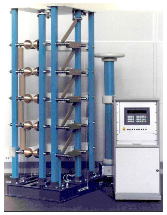
Highvolt Impulse Voltage Test System (100KV to 1200KV)
Features
The impulse
voltage generators / series L are the main component of impulse voltage test
systems, series L (see Data Sheet 3.10),
ranging from 100 kV to 1200 kV cumulative charging
voltage.
They are designed for testing high-voltage equipment of power systems with lightning impulses
(LI: 1.2/50 µs) and switching impulses (SI 250/2500 µs)
according to the IEC standard 60060-1 (IEEE St.4). The maximum charging voltage is 100 kV per stage with a
maximum energy of 5 kJ per stage. With 12 stages, maximum output voltages of 1150
kV (LI) and 900 kV (SI)
can be generated in the no-load case.
The impulse
voltage generators can be modified for carrying out a variety of special tests,
e.g. on transformers, impulse current
testing of surge arresters as well as EMP tests of electrical equipment. The
chosen modular system enables
a very variable application
in industries as well as in laboratories for research and education.
The circuit
of the impulse voltage generators is the Marx multiplier circuit.
The impulse capacitors, arranged in the stages
of the impulse voltage generator, are charged in parallel with DC voltages up
to 100 kV against earth potential
and, in order to generate impulses, connected in series by spark gaps. For the
adjustment of the front time and time
to half value of the test impulse, the generator stages comprise front
resistors and tail resistors. A short discharge loop guarantees low internal inductances and smooth voltage shape.
The impulse
voltage generator is constructed in five-column design. All of these columns
are made of glass-fiber reinforced
plastic support; three of them serve as supports for the impulse capacitors in
the generator stages. All necessary
front and tail resistors are arranged between one of the three columns and a
fourth column. At the fifth column
the fixed sphere gaps and the charging resistors of each stage are arranged.
The movable sphere gaps are fixed
together at a vertically arranged insulating bar, which can be horizontally
moved for adjustment of the gap
distance with the help of a motor
drive on earth potential.
The five
insulating columns are placed on a common sectional steel base which is
designed either as stationary or as a mobile type.
SKU: High Volt
Category: High Voltage Lab Equipment, High Volt
Table 1: Electrical Main Parameters
Stage Energy (1) | 2.5 kJ | 5 kJ | |||
| Total Charging Voltage (KV) | Number of Stages | Total Charging Energy (kJ) | Impulse Capacitance (nF) | Total Charging Energy (kJ) | Impulse Capacitance (nF) |
| 100 | 1 | 2.5 | 500 | 5 | 1000 |
| 200 | 2 | 5.0 | 250 | 10 | 500 |
| 300 | 3 | 7.5 | 167 | 15 | 333 |
| 400 | 4 | 10.0 | 125 | 20 | 250 |
| 500 | 5 | 12.5 | 100 | 25 | 200 |
| 600 | 6 | 15.0 | 83 | 30 | 167 |
| 700 | 7 | 17.5 | 71 | 35 | 143 |
| 800 | 8 | 20.0 | 63 | 40 | 125 |
| 900 | 9 | 22.5 | 56 | 45 | 111 |
| 1000 | 10 | 25.0 | 50 | 50 | 100 |
| 1100* | 11 | 27.5 | 45 | 55 | 91 |
| 1200* | 12 | 30.0 | 42 | 60 | 83 |
| Min. time difference between impulses | 20 s | 40 s | |||
| Capacitors per generator stage | 1x0.50uF/100 kV | 1x1uF/100 kV |
*) Only stationary
1) Other stage energies resp. other min. time difference between impulses on request.
Main Parameters
Total charging voltage: 100 to 1200 kV
Total charging energy: 2.5 to 60 kJ
Stage charging voltage: 100 kV
Stage energy: 2.5, 5.0 kJ
Number of stages: 1 to 12
Table 2: Dimensions, weights
| Total charging voltage | Number of stages | Height H installation | Base frame Length x Width LxB mm | Weight kg | ||
| kV | mm | Stage energy 2.5kJ | Stage energy 5 kJ | Stage energy 2.5kJ | Stage energy 5 kJ | |
| 100 | 1 | 1050 | 1060 x 835 | 1425 x 835 | 252 | 327 |
| 200 | 2 | 1390 | 313 | 423 | ||
| 300 | 3 | 1730 | 375 | 520 | ||
| 400 | 4 | 2070 | 436 | 616 | ||
| 500 | 5 | 2410 | 498 | 713 | ||
| 600 | 6 | 2750 | 560 | 810 | ||
| 700 | 7 | 3090 | 621 | 906 | ||
| 800 | 8 | 3430 | 683 | 1003 | ||
| 900 | 9 | 3770 | 744 | 1099 | ||
| 1000 | 10 | 4110 | 806 | 1196 | ||
| 1100* | 11 | 4450 | 868 | 1293 | ||
| 1200* | 12 | 4790 | 929 | 1389 |
Safety clearance D (see dimensional drawing)
D is approximately height H / 2.
Please note:
D depends on wave shape (LI, SI,..), dimension of top electrode
and dimension of test hall.
Mobility
Impulse voltage generators with voltages from 100 to 1000
kV are moveable as option.
Impulse voltage generators with voltages of 1100 and 1200 kV are only stationary systems.
Accessories on special request
Set of resistors for switching impulse
test of transformers
Roller skates
for the impulse voltage
generator, in order to move it by hand (up to
1000 kV)
Additional resistors and inductances (Glaniger Extension, Data Sheet 3.32) for the lightning
impulse voltage test of transformers
Reactors for the generation of oscillating lightning and
oscillating switching impulses, e.g. for the on-site testing of SF6-switchgear
Reactors for the generation of impulse currents,
e.g. for the testing of surge arresters
and components of lightning
protection or for the generation of impulse magnetic fields
Weather-protecting hood for a
temporary outdoor installation of the generator
The generator can be equipped with a motor-driven earthing rope, which additionally short-circuits all impulse capacitors after the generator is switched off
Type designation
IGF a/b L
A = total
charging energy in kJ
= stage energy in kJ x number of
stages
b = total
charging voltage in kV
F =
mobile (on roller skates for series L) Without F = stationary
L = series
L (light)