EV AUTOMATIC POWER FACTOR CORRECTION SYSTEMS Mod. C-PF/EV
Features
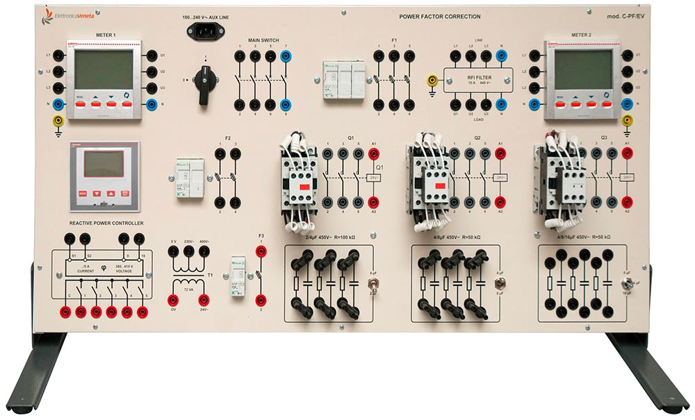
This panel enables the experimentation on industrial installations with electronic devices for the control of power factor correction of electric low-voltage uses (voltage of 400 V). Automatic power factor correction circuits with different capacitive steps controlled by an electronic unit can be assembled on the panel. Two power analyzers measure voltages, currents, active, reactive and apparent powers and power factor.
The instruments are confi gured in 3 single-phase, three-phase systems with or without neutral; their use is free in the circuit: e.g.: in the feed line, in users or power consuming facility, in a capacitive battery, etc…
The panel is made of insulating material where components are represented with their international electric symbols; electric connections are easier via cables and jumpers with safety plugs of 4 mm; no tool is used.
The electric user with different values of apparent-active inductive power is easily reproduced in laboratory with the combined help of variable resistive-inductive loads.
A value of active-reactive power ranging between 1300-1900 W + 1300 - 1900 Var, adjustable in 5..7 steps, is recommended for a very good experimentation.
Variable loads mod. RL-2/EV + IL-2/EV, or mod. RL-3/EV +IL-3/EV, or mod. RL-2K/EV, are recommended.
SKU: Machines
Category: Electrical Machines, Power Generation, Distribution & Consumption
TECHNICAL CHARACTERISTICS:
- Varnished metal framework with fore panel of insulating material.
- Quick connections via safety terminals and cables Ø 4 mm
- 1 automatic microprocessor-controlled power factor regulator, with rated voltage 380-415 V 50-60 Hz
- ammeter input with forward current up to 5 A (sensitivity range 0.125..6 A)
- setting power factor 0.8 ind…0.8 cap, reconnection time 5…240 s
- sensitivity range 5…600 s/step
- 5 relay outputs with contacts 5 A - 250 Vac
- manual setting of parameters by display-assisted keyboard
- 2 multi-function instruments, with auxiliary power supply of 115-230 V, 3 lines of three 7-segment displays of 13 mm with red LEDS
- measures of voltages, currents, active-reactive-apparent powers and power factor in single-phase and three-phase systems
- accuracy class for currents and voltages ± 1%
- measuring range: 5 A - 850 V max
- operational four-pole rotary switch of 16 A - 400 V
- 1 set of three fuse holders with gl-type fuses 10.3 x 38 of 6 A
- 1 pair of fuse holders with gl-type fuses 10.3 x 38 of 2 A
- 1 fuse holder with gl-type fuse 10.3 x 38 of 4 A
- 1 noise suppressor for three-phase line with neutral - Un 440V, In 10 A, inductance 0.4 mH, capacitance 0.1 μF.
- 3 three-pole contactors for power factor correction Ith (AC1) 25 A (7.5 kvar at 400 V) with transient limiting devices, insertion, excitation 24 Vac 50-60 Hz
- 1 single-phase transformer -primary 230-400, secondary 24 V, power of 72 VA
- 1 battery of three-phase capacitors of 450 V∼ with selector between 2 and 4 μF and corresponding discharge resistors of 100 Ω - 5 W
- 1 battery of three-phase capacitors 450 V∼ with selector between 4 and 8 μF and corresponding discharge resistors of 50 Ω - 10 W
- 1 battery of three-phase capacitors 450 V∼ with selector between 4.8 and 16 μF and corresponding discharge resistors of 50 Ω - 10 W
- All the batteries of capacitors can be connected in single-phase configuration or in three-phase star-delta configuration, they enable the development of automatic power factor correction systems up to 3 equal steps (4 + 4 + 4 μF), up to 3 double steps 2, 4, 8 μF, or of 4, 8, 16 μF; further combinations are possible from the parallel connection of the various batteries.
- Dimensions: 805 x 405 x 100 mm
- Net weight: 18 kg
OPTIONAL ACCESSORY:
Software and programming cable (having to be ordered separately). Adding the programming software, via port RS232 (or USB with a converter) will enable to set and display (simultaneously) all the measures (current power factor, set power factor, average weekly power factor, voltage, current, reactive power of the installation) in the automatic power factor regulator in order to get a general view of power factor correction system. Moreover, the total time and the number of insertions performed from the start of the installation are shown for each step, for the preventive maintenance of contactors.